


Norme Vigenti | Tecniche Costruzioni 2008 PDF | NTC 2008 Circolare 2 febbraio 2009 | Circolare 617/0 CRJ: Nodo cinetico multidirezionale d’angolo
CRJ: ANGLE MULTIDIRECTIONAL KINETIC NODE
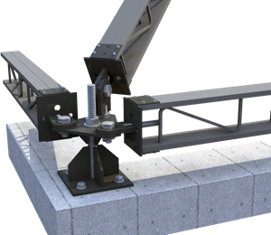
Description of the CRJ node
The CRJ - Corner Roof Joint - is made up of six articulated elements. The element A is formed by the support plate and a bolt that connects the plates A and B; the element B is the plate to which the elements C / C1, C2, and C3 are connected, which are used to join the beams of the covering, be they the perimeter ones or the struts. The CRJ allows the rotation of the perimeter roof beams in the XY plane while the strut can rotate in the vertical plane.
The CRJ is made in the workshop in compliance with the UNI standards relating to the chemical composition of steels and welding processes (UNI EN ISO 4016: 2002, UNI 5592: 1968, UNI EN ISO 898-1: 2001, UNI EN 20898-2: 1994). The screws and bolts are made of high-strength steel class 8.8 and the rest of the elements are made of S355 steel. To guarantee greater durability, all the elements are subjected to a hot-dip galvanizing process.
Calculation hypothesis
Joint stressed by compression and tension traction in correspondence of the holes that connect the node to the underlying wall. The constraint has three degrees of freedom on the rotations in the XY, XZ and YZ planes and does not allow movement. The stress F varies for each rod and depends on the actions transmitted by the beams of the roof: on the element C1 acts a force equal to -1.64F, on the element C2 acts a force equal to -1.00F and on the element C3 acts a force equal to + 0.50F.
Calculation results
The results were obtained with a non-linear analysis of the stress / strain state and of the displacement / deformation behavior, performed with a finite element calculation program for incremental load values. The characteristics of the materials are as follows: S355 steel plates; high strength screws and bolts 8.8. The results of the tests carried out refer to the action of three forces (F1 / F2 / F3) for four distinct inclinations (a) of the node, arbitrarily chosen; the angle of rotation of the joint is α = 15 °, 30 °, 45 ° and 60 °. The compressive forces (F1 / F2) and the tensile forces (F3) reach the following stress values:
Where: Se = Max stress at the elastic limit.
Ss = Max stress at the complete plasticization of the resistant section.
Results of the force F expressed in Newton (N) equal to 10 N = 1 Kg.